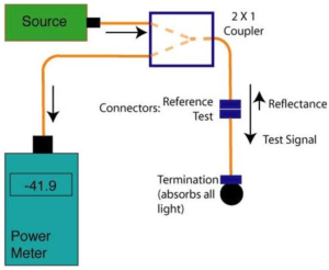
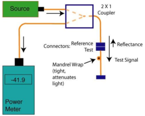
We use the established optical CW reflection (OCWR) method to measure optical return loss.


As shown in the figures above, the OCWR Testing setup for reflectance or return loss tests of connectors or passive fiber components per industry standards (TIA FOTP-107 or IEC 61300-3-6) using a light source and power meter. The method sends light from a source through a coupler to the fiber components that are being tested. That connection will typically consist of a reference connector which is used to mate to the connector under test. The light reflected from that connection is split by the coupler, and part is measured by the power meter.
In order to calculate the reflectance or return loss, you need to know the magnitude of the test signal and the split ratio of the coupler, including the excess loss of the coupler. The coupler will reduce the outgoing and reflectance power levels by 3 dB plus some loss due to its inefficiency, typically ~ 3.5 dB.. You must also minimize the reflectance of other components in the cable under test. There are two ways often used to “terminate” or reduce the reflectance from the rest of the cable under test. One method is to use an “optical termination” at the end connector, typically done by inserting the end of the connector ferrule into an index matching gel or liquid. The index matching gel used for mechanical splices works well, but mineral oil or alcohol works fairly well too. The other method is to use a mandrel wrap to reduce the reflectance from other ports. After the test, of course, the connector ferrule needs careful cleaning with pure isopropyl alcohol.
