To measure the insertion loss of a single-mode fiber optical device, follow these steps to ensure accuracy and reliability:
1. Preparation
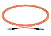
- Fiber Optical Jumper Cable: Create a fiber optical jumper cable that matches the fiber type and connectors used in the device under test. This jumper will be used for calibration purposes.
.

2. Laser Source Preparation
- Laser Type: Use a stabilized laser that matches the specifications outlined in the purchase order (PO) or datasheet. The laser should have a feedback controller to ensure stable output.
- Optical Isolator: Employ an optical isolator to prevent instability caused by back reflections.
- Laser Characteristics: Be aware that different types of lasers (single-mode with sharp peaks or broadband) and multimode lasers can affect measurements differently, particularly impacting return loss and effective reflection.
- Polarization Maintenance: For devices requiring polarization maintenance, use a fiber laser-based polarization-maintaining (PM) light source with both power and extinction ratio (ER) stabilized for optimal accuracy.
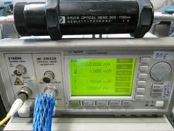
- Optical Power Meter: Use a benchtop optical power meter, such as those from Agilent. Ensure it has large area detector heads (silicon for shortwave, germanium for IR) for accurate measurements.

3. Calibration
- With Optical Connectors: Connect the fiber jumper cable in place of the device to be tested. Zero the optical power meter. It should read 0.00 dB. This ensures that the meter is properly calibrated for connector losses.
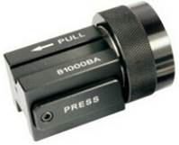
- With Bare Fibers: If testing a device with bare fibers, insert the bare fiber end of the laser into the large area detector head using an Agilent bare fiber adapter. Zero the meter, ensuring it reads 0.00 dB. This step calibrates the meter to account for the bare fiber’s characteristics.

4. Measurement
- For Devices with Connectors: Replace the fiber jumper cable with the device to be measured. The optical power meter will display the insertion loss. Note that this method may introduce errors due to connector variations.
- For Devices with Bare Fibers: Perform a splice between one end of the device and the laser, then insert the other end into the large area detector head using the Agilent bare fiber adapter. The optical power meter will display the insertion loss, offering a more accurate measurement by eliminating connector losses.
Additional Tips
- Consistency: Ensure that all connections are clean and properly aligned to minimize measurement errors.
- Documentation: Record the measurement conditions, including laser type, wavelength, and any deviations observed during testing.
- Repeat Measurements: For greater accuracy, consider performing multiple measurements and averaging the results.
By carefully following these steps, you can achieve reliable and accurate measurements of insertion loss for single-mode fiber optical devices.
